My 2012 Solidoodle 2 Pro 3D printer’s original extruder got irreparably clogged, so I needed to replace the hotend. I decided to go with an E3D v6 1.75mm hotend (USA). This necessitated upgrading/replacing the power supply as well.
Tools
- wire stripper (capable of stripping 16 AWG insulated wiring)
- wire cutter (frequently part of a multipurpose wire stripper)
- normal Phillips-head screwdriver
- small flat-head screwdriver
- multimeter (capable of measuring voltage in the range of 12V)
Parts
- 12V 30A 360W DC power supply (12-volt, 30-amp, 360-watt, direct current); as suggested, I picked this one
- 3 feet (1 meter) of 2-conductor or 3-conductor 16 AWG insulated power cable
- normal-length pronged (wall plug) power cable, like the one currently connecting your 3D printer to wall power (16 AWG or 18 AWG)
- some extra electrical/electricians tape
Cut off the end of the power cable farthest from the outlet plug.
The three wires inside are white (neutral), black (line/load), and green (ground).
Strip back the outer insulation a couple inches.
Strip each of them about 1 inch.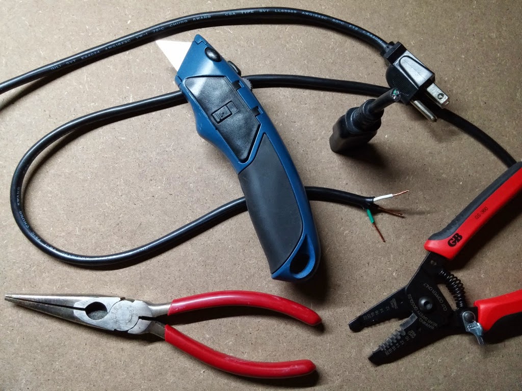
Locate the power supply’s input terminals, labelled ground (⏚ upside-down Christmas tree icon), neutral (N), and , line/load (L).
Attach the wires correctly: green to ground, white to neutral, and black to line/load. Simply loosen/unscrew the screws on the power supply (you don’t have to unscrew them entirely or take them off), carefully put the uncovered wire in, and re-tighten the screws (hand-tightened is enough; don’t overdo it).
Make sure the power supply is set to the correct voltage. Normal household electrical voltage in the United States is 110V-120V.
Locate the small, green, two-connector power terminal on the Solidoodle 2 Pro control board. It is at the end of the power supply cable currently connected to it.
Check the positions of the power cable wires *WRITE DOWN WHICH WENT WHERE* (i.e. black on top or bottom)!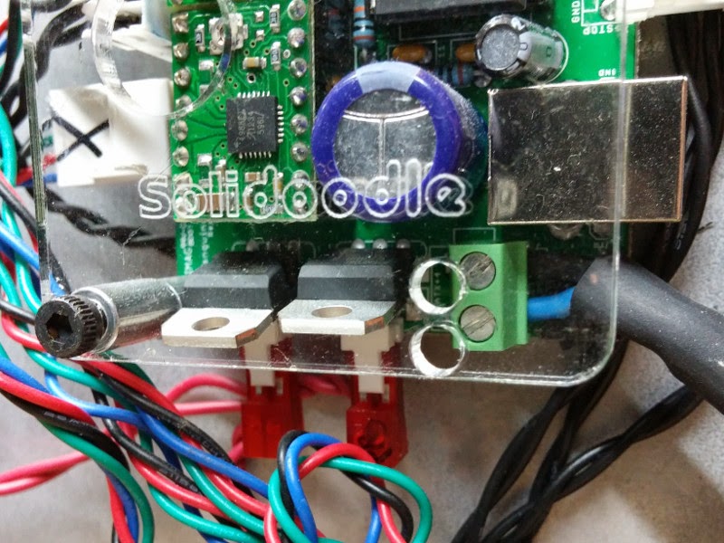
Carefully loosen each screw on the terminal enough to take the power cable wires out but not enough for the screws to come out or the terminal to come off the board. It is just a weak little plastic terminal, so avoid abusing it; it can break.
Take the power cables wires out of the terminal, pulling gently.
Un-tape the old/original power supply and its cable from the printer (you don’t have to take the tape all the way off) and set the printer aside.
Get out the multimeter and measure the voltage between the power cable wires while the old power supply is plugged into wall power. If you do not know how to do this, then read the manual that came with your multimeter (if you still have the manual) and watch “THE BEST Multimeter tutorial (HD)” by Afrotechmods, on YouTube.
Unplug the old power supply from wall power and plug in the new power supply to wall power. Immediately unplug it if you hear, smell, or see anything out of place (e.g. pops, burning, smoke) to indicate that you did not wire up the power supply correctly.
Use the multimeter to measure the voltage between the output terminals and make sure it is 12V. If you accidentally got a 5V or 24V power supply and try to use it here, then you’re gonna have a bad time.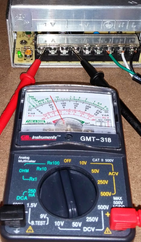
Prepare your new power supply-to-printer 16 AWG power cable by stripping a few inches of insulation off the ends and getting the individual wires sufficiently separate to connect to the correct terminals. The wires to go to the printer need to be carefully cut to the same length, otherwise connecting them will be difficult.
Unplug the new power supply from wall power if you haven’t already. Wait for it to be completely off.
Connect the supply-to-printer power cable to the new power supply output terminals.
Take note of exactly which wire (by color or texture) you connected to which terminal (positive or negative).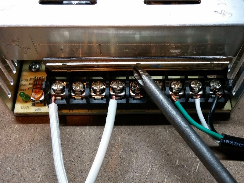
[OPTIONAL] You can plug the new power supply into wall power and use the multimeter to check which wire is positive and which is negative if you have to.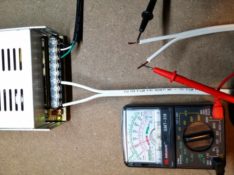
Being extra careful, connect your new power supply wires to the positions of the old ones (i.e. new positive wire to old positive terminal position) by putting the new wire in the terminal and holding it there while you gently tighten the screw to hold it in place. Over-tightening the screws can break/split the small, green, plastic terminal. If you are using stranded (as opposed to solid) wires, then you will need to twist them together a bit to keep them sufficiently together to get all the strands into a terminal.
Plug the new power supply into wall power. Immediately unplug it if you hear, smell, or see anything out of place (e.g. pops, burning, smoke) to indicate that you did not wire up the power supply correctly.
If your wiring is correct and the printer powers on as expected (e.g. the lights and fans turn on), then you can unplug it again and tape the power supply-to-printer power cable to the printer.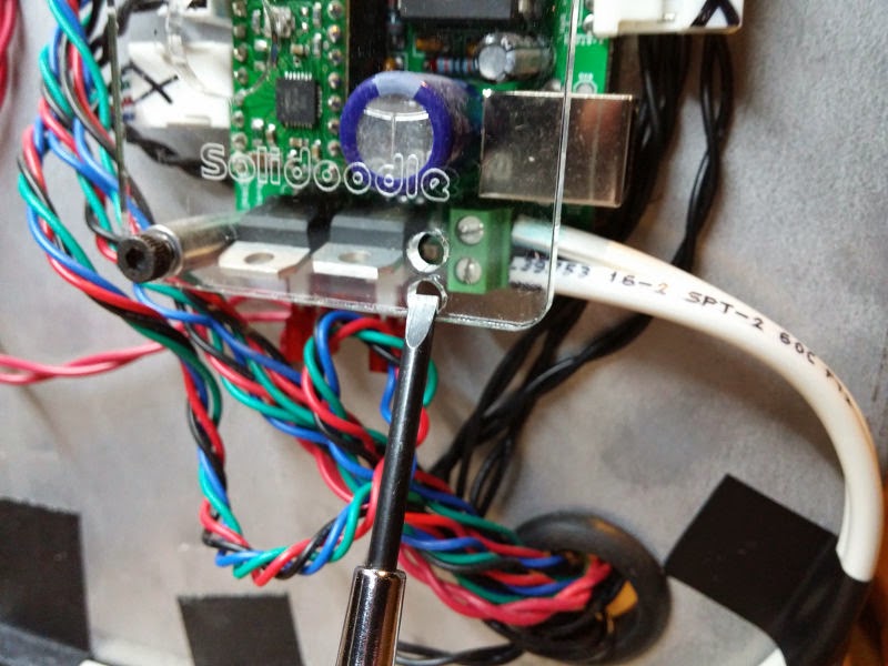
Sources
- “Upgrade The Power Supply” by HunterGreen, on the Community Solidoodle Wiki
Additional Material
- “Wire Gauge Reference Table” on Powerwerx
- “Wiring Color Codes” on All About Circuits
- “THE BEST Multimeter tutorial (HD)” by Afrotechmods, on YouTube
- “American wire gauge” on Wikipedia
- “How Electricity Works” by Marshall Brain, William Harris and Robert Lamb, on How Stuff Works » Science » Physical Science » Electricity
I have noticed that on all of the tutorials for this upgrade, none of the PCBs shown have a cylindrical power port. Mine, however, does. The power port on my unit resembles the female power port on a laptop. For this reason, I am at a complete loss on how to attach the new power supply to my PCB. Do you have any thoughts on how I can complete the upgrade?
How were you connecting the old power supply? IMHO, the simplest solution would be to salvage an appropriate cable (correct male connector already on it, correct gauge, etc.).
The "female power port on a laptop" is called a "power jack" if you're shopping for them.
– http://www.laptopking.com/dcjacklist.asp
The male power plugs can also be acquired separately, if you know exactly which you are looking for…
– http://www.mouser.com/Connectors/Power-Connectors/DC-Power-Connectors/_/N-axitt?P=1z0vlpq
A tool that's accustomed live volts, amps and ohms is termed a digital multimeter. These tools don't seem to be an equivalent as analog meters, that have needles and gauges. Digital multimeters have digital junction rectifier displays. These sorts of multimeters ar usually a lot of correct compared to the recent analog varieties garage tools.