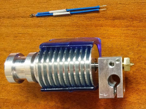
My 2012 Solidoodle 2 Pro 3D printer’s original extruder got irreparably clogged, so I needed to replace the hotend. I decided to go with an E3D v6 1.75mm hotend (USA). I already upgraded the power supply, removed the original extruder, and assembled the new hotend (see previous posts). Now was the time to actually install it.
Previous Posts
Tools
- 2.5mm hex key
- 4mm hex key
- small, slant tip tweezers
- wire cutter
- wire stripper (for 22AWG and 26AWG)
- heat source for heat shrink (I used a candle lit with matches; a lighter also works)
- adjustable spanner
- small 7mm hex socket wrench
Parts
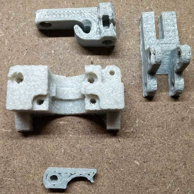
- Lawsy’s Mk5 extruder housing; if you cannot print one ahead of time (alternative design) then you can also order a temporary one.
- three lock nuts and some bolts scavenged from a disassembled original Solidoodle 2 Pro acrylic jigsaw extruder housing (used to assemble the extruder housing); the scavenged bolts you will need are the M5x15mm bolt (held the ball bearing and washers in the tension arm), two M3x22mm bolts (from the jigsaw body), the M3x20mm bolt (held the tension arm to the body with a lock nut), and the M3x30mm bolt (also from the tension arm; had the spring over it)
- a M3x8mm bolt and an additional M3x20mm bolt (I found these bolts purchasable individually from a local ACE hardware store)
- the 20-22AWG connector from the end of the heater wire scavenged from a disassembled original Solidoodle 2 Pro extruder
- 2 pairs JST male-female connectors, 22AWG wire; I used these
- 2x pieces of 3mm and 4x pieces of 2mm or 3mm heat shrink tubing; I used all 3mm pieces from these
- some extra electrical/electricians tape
- some small twist and/or zip ties to tidy up the final wiring
Printer Information
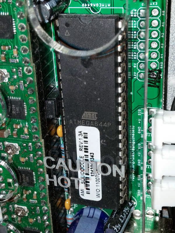
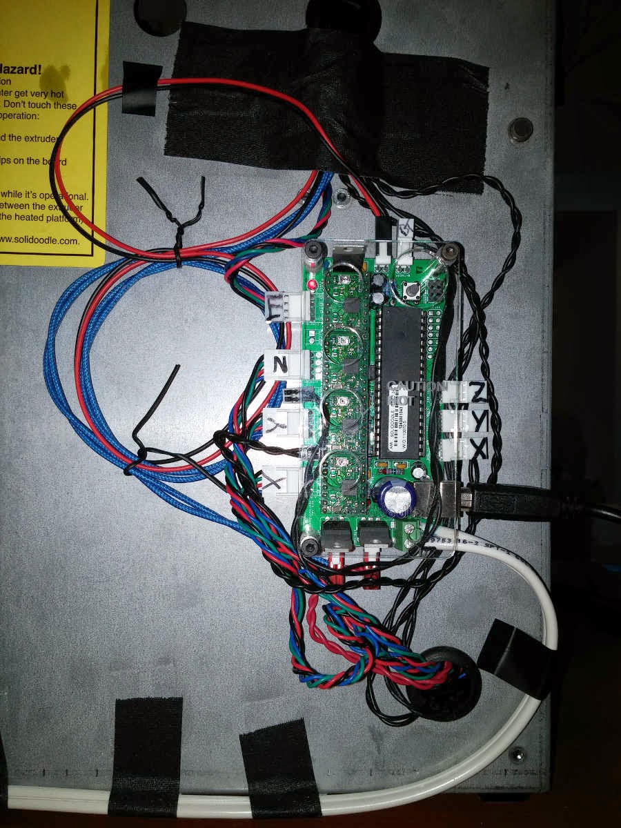
My 2012 Solidoodle 2 Pro circuit board is a Sanguinololu and it has an ATMega 644P processor — the processor is named on the chip and on the board above the chip while the board is named to the side of the chip (“reprap.org/wiki/sanguinololu“). It is running Marlin firmware which can be found on GitHub, according to the Repetier-Host (Solidoodle V0.85b) software — Connect, then Printer > Printer Information. My Repetier-Host printer settings shows that the printer is using the COM5 port.

- If this printer + board + processor is not exactly what you have then seriously consider finding a different blog post / tutorial / information source for this process.
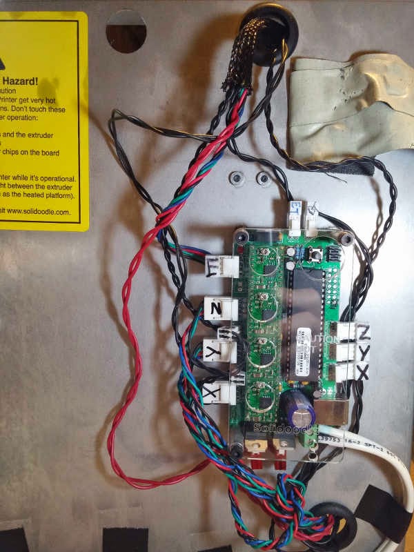
Circuit Board Terminals

Listed top to bottom and left to right.
TOP:
2-pin “ET” extruder thermistor thermal/temperature sensor
2-pin “BT” heated print bed thermistor thermal/temperature sensor
LEFT:
4-pin “E” extruder filament feed motor
4-pin “Z” up-down print bed motor
2-pin LED power
4-pin “Y” forward-back print head (extruder) motor
2-pin fan power
4-pin “X” left-right print head (extruder) motor
RIGHT:
3-pin “Z” top contact position sensor
3-pin “Y” back contact position sensor
3-pin “X” right contact position sensor
USB printer port
BOTTOM:
2-pin extruder heater power
2-pin print bed heater power
2-connector power supply input
Original Extruder Wiring
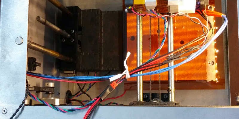
There are four sets of wire which go from the circuit board through the wire sleeving through the top hole in the back of the printer:
- The RGBB (red, green, blue, black) wire bundle connects the extruder filament feeder motor into the top 4-pin terminal at the left of the circuit board.
- The red wire pair connects the extruder heater into the left 2-pin terminal at the bottom of the circuit board labelled “PWR1” on the board.
- The fully/entirely black wire pair connects the extruder thermistor into the left 2-pin terminal at the top of the circuit board.
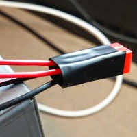
- The other black wire pair at the back is connected with heat-shrink to a red and black wire pair. This wire pair connects the extruder motor heat sink fan into the bottom 2-pin terminal on the left of the circuit board, just below the 4-pin “Y” terminal.
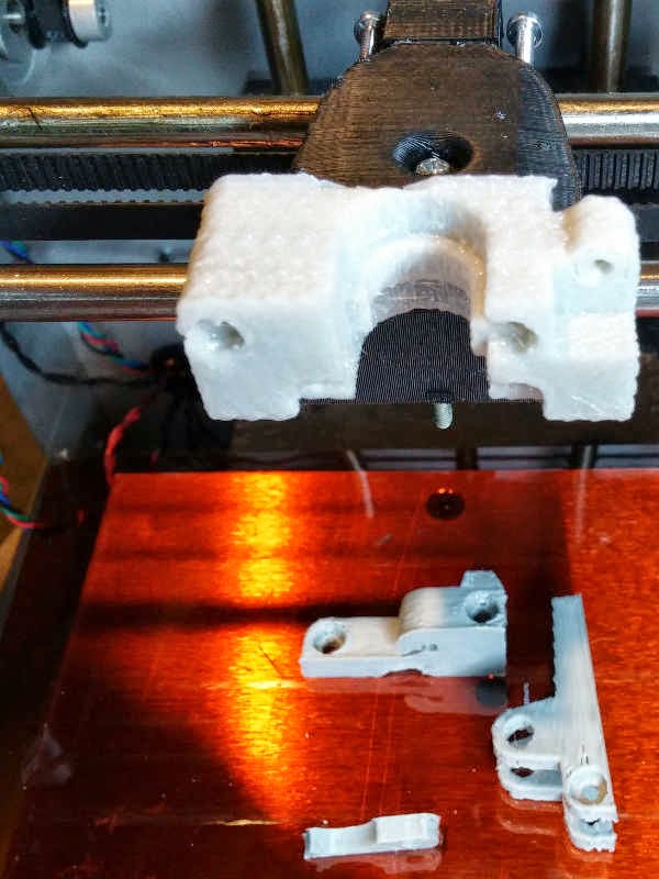
Physical E3D v6 hotend installation
Since my printer had already become inoperable, I had to order a temporary replacement extruder housing. Fortunately, such a thing is available from/through Filastruder [LINK]. There have been some updates to the design over time and that locking arm is actually not used/necessary when mounting an E3D v6 hotend.
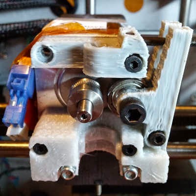
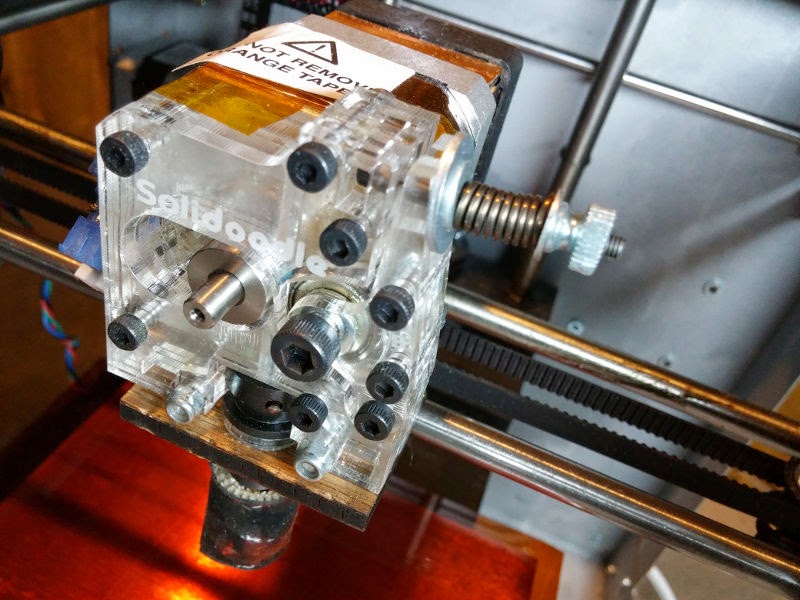
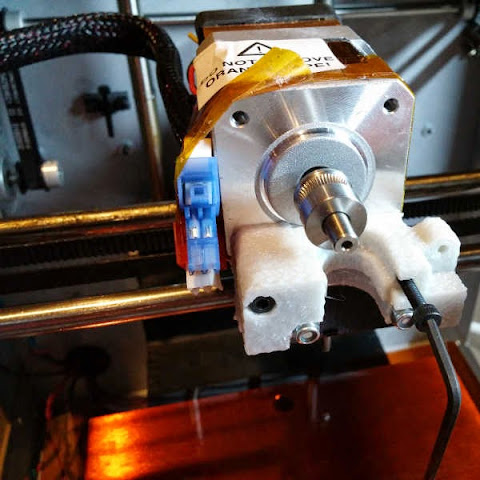
Start by getting the extruder assembly hotend mount body attached to the carriage using the same two long bolts and lock nuts that held the original extruder on.

With the extruder assembly hotend mount body securely attached to the carriage, you can now attach the extruder stepper motor to the extruder assembly hotend mount body using two M3x22mm bolts.
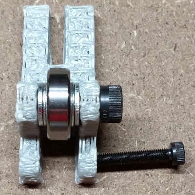
Get the tension arm set up with the ball bearing sandwiched between the 4 washers on the M5x15mm bolt.

Attach the arm to the body using a M3X20mm bolt secured with a lock nut. Install the M3x30mm tension bolt with its spring (from the arm going out: M5 washer, M3 washer, spring, M3 washer, thumb nut). The outer hole of the thumb nut was supposed to be flush with the end of the tension bolt in order to provide sufficient tension in the original acrylic jigsaw extruder housing. The 3d printed Lawsy tension are is a millimeter or two thicker, so the thumb nut should be a little farther out to avoid excess tension.

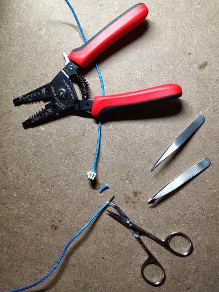
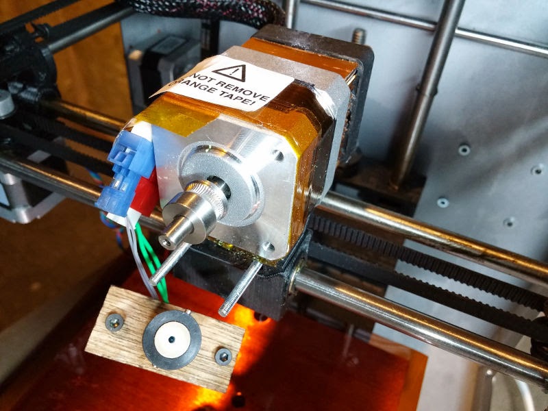
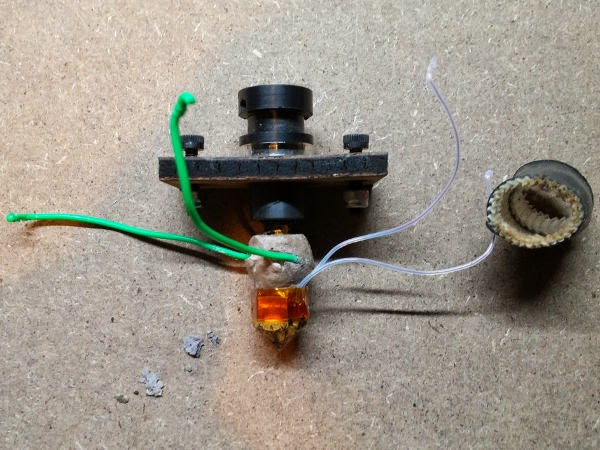
The wires from the E3D v6 heater and fan do not have connectors on them yet. I reused a connector scavenged from the original Solidoodle 2 Pro extruder here for the E3D v6 heater. I got the wire set into the connector by stripping the insulation by about 5mm, twisting the stranded wire a bit to keep it straight, carefully inserting it straight into the connector (parallel to the pin ports on the other side), and then pulling the wire 90 degrees to catch it in the connector’s grip. I used some tweezers to push it down a bit more.

– Untape the wires coming out of the upper hole in the rear of the Solidoodle 2 Pro case.
– Unplug the 4 wire connectors from the circuit board for the wires held by the braided cable sleeve.
– Compressing the sleeve lengthwise expands its diameter, enabling you to take if off. Remove the braided cable sleeve.
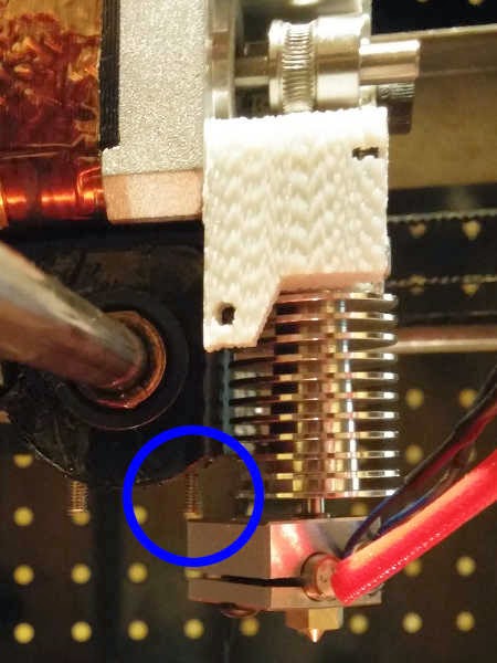
– Look at the bottom of the extruder carriage and note that it has 2 bolts sticking far down through it. Do not push the aluminum heating block into that bolt when putting the E3D hotend into the extruder housing body.
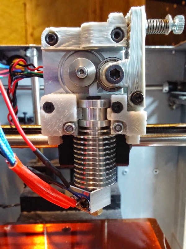
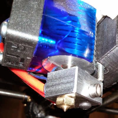
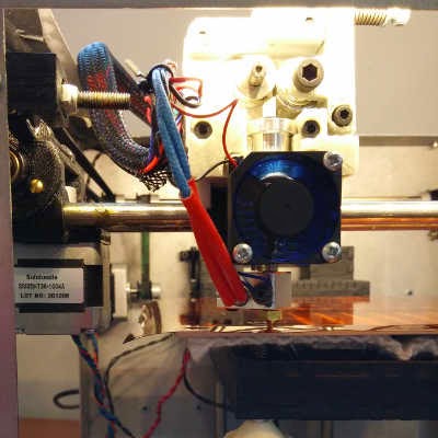
– Carefully push the E3D v6 hotend, without its fan duct, into the Lawsy Mk5 extruder housing body *WITHOUT* pressing on the aluminum heating block or pressing the block into the forward bolt sticking down through the extruder carriage. The heat break connecting the heat sink to the heating block is fragile so you have to only push on the heat sink to get the hotend into the extruder housing.

Once the hotend is in the body, you can twist it relatively easily. Twist the hotend so that all the extruder wires are on the same side, but avoid twisting the heating block into the carriage bolt.

Clip the E3D v6 hotend fan duct onto the heat sink so that the flat side of the duct is flush with the bottom of the heat sink. Attach the fan to the fan duct such that the fan’s wires come out of its top left AND the fan is blowing into the fan duct into the heat sink. There should be a small arrow etched into the fan housing showing the direction the fan blows. Avoid pressing on the fan itself (as opposed to its housing) as it is fragile.
Use a little electrical tape to hold 2 JST female connectors together.

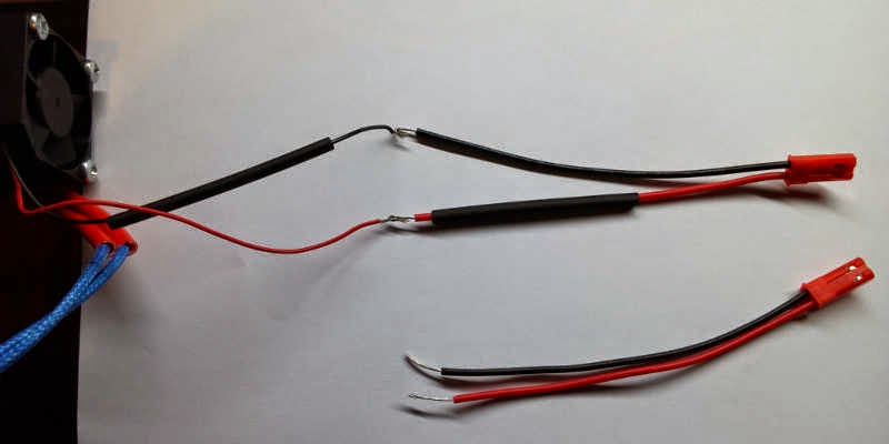
– Find the wire pair that was powering the extruder stepper motor heat sink fan from the circuit board fan power terminal and was spliced directly to that fan with heat shrink. The JST connectors need to be spliced into it so that it powers two fans — both the stepper motor heat sink fan and the new E3D v6 hot end heat sink fan. Keep track of which wire was spliced to the red fan wire.
– Cut the fan spliced fan power wire apart on either side of the heat shrink splice.
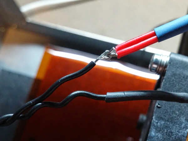
– Strip 5-6mm of insulation off of the end of the JST connector wires, the wires from both fans, and the wire pair that used to connect to the fan power terminal on the circuit board.
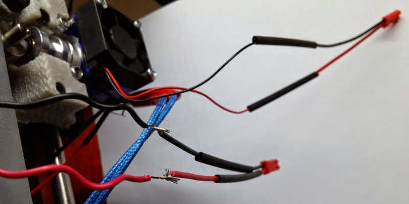
– Twist the ends of the wire strands a bit so they stay together better.
– Get a new piece of [3mm-4mm] heat shrink slid over both red wires from the JST female connectors.
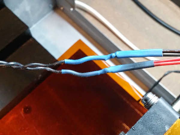
– Twist together or hook and close together the uninsulated wire ends of the red wires from the JST female connectors to the fan power terminal wire which was previously spliced to the red wire from the extruder stepper motor heat sink fan.

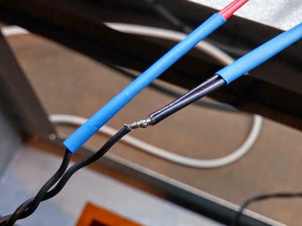
Repeat the previous step, this time splicing the black wires from the JST female connectors to the fan power terminal wire which was previously spliced to the black wire from the extruder stepper motor heat sink fan, using another piece of [3mm-4mm] heat shrink.

Heat the heat shrink to shrink it and seal/fit it over the splice to insulate/protect the splice. I used a candle, but any sufficiently hot heat source will work. Your heat shrink should indicate its minimum and full shrinkage temperatures — mine is 70°C – 110°C. Open flames can and will burn heat shrink, so don’t let the heat shrink stay above the flame for too long so it doesn’t overheat. The heat shrink *does not* need to be *in* the flame — ~4″ (inches) above the flame is plenty close enough. You do not have to heat it all the way closed all at once. I found success by repeatedly holding the heat shrink above the flame until it starts to change then immediately removing it from the heat to see how much it closed/shrank.

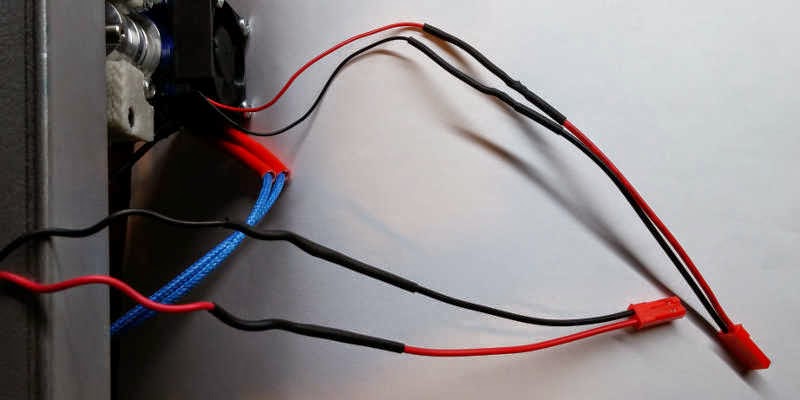
Splice a JST male connector to the E3D v6 heat sink fan using two more pieces of [2mm-3mm] heat shrink.

Splice a JST male connector to the extruder stepper motor heat sink fan using two more pieces of [2mm-3mm] heat shrink.

Heat and seal the heat shrink over the fan wiring splices.

You do not need to finalize the wiring yet, but you do need it out of the way. I just reused a twist tie from some grocery store produce here, temporarily.

Plug the printer back into wall power, but be ready to immediately unplug it if anything goes wrong.
– There should be no sparks, smoke, new smells, etc.
– Check that both heat sink fans are spinning.
- If the fans do not appear to be spinning as much as they should then you can try wiring them directly to the power supply, rather than the circuit board. They both need to be blowing the entire time the printer is on anyway.
Marlin firmware update/modification for the E3D v6 hotend using Windows 7
* NOTICE: This is exclusively for if you exactly have a Solidoodle 2 Pro 3d printer with a Sanguinololu circuit board and an ATMega 644P processor. Blindly guessing at what changes you need to make here if you have anything else is probably a terrible idea. *
The “Firmware Updates” section of the “E3D extruder” page/article on SoliWiki worked well enough for me.
1) Have the FT232R USB UART Arduino USB driver installed.
– I already had this installed. If you do not, then you can check the original Solidoodle “How to Install Software“, the Solidoodle Customer Service & Technical Support article “Installing Drivers“, and/or the Arduino learning/documentation guide/article “Getting Started with Arduino on Windows“.
2) Have the version 0022 Arduino compiler and utilities tools.
– Later versions, either directly installed or by letting the Arduino software update itself, will not work with the Solidoodle 2 Pro.
– The Arudino software/code/project was on on Google Code, but migrated to be on GitHub.
3) Have the Sanguinololu repository [from GitHub] and Solidoodle 2 Marlin firmware code [from GitHub].
– The Sanguinololu folder from the Sanguinololu repository needs to be copied into the hardware directory of the Aruduino software. Neither the Arduino software nor the Marlin firmware code/project need to be anywhere specific.
4) Have the Arduino software set up for your Solidoodle 2 Pro 3d printer. This involves 1 recommended and 2 necessary changes:
– File > Preferences > uncheck the box “Check for updates on startup”
– Tools > Board > select the “Sanguinololu w/ ATMega644P” board and processor
– Tools > Serial Port > select the COM port the printer is using
If you do not see the printer’s COM port listed, then close the Arduino software, unplug the printer USB and power, and then plug in the printer power and USB cables. Your operating system (Windows 7 for me) should recognize the new device and load its driver. Open Repetier-Host to double-check which COM port you are looking for, then open the Arduino software again and that COM port should be listed.
5) Test that the unmodified firmware code/project compiles with your setup.
– File > Open > browse to the unarchived firmware source code folder > select the file “Marlin.pde”
– Sketch > Verify/Compile [Ctrl+R]
The Arduino software should say “Done compiling.” in black letters in the light blue area below the code/file/text area, and “Binary sketch size: 49378 bytes (of a 63488 byte maximum)” in white letters in the scrollable black area near the bottom of the Arduino software window.
6) Edit the file “Configuration.h” to updated temperature values/settings for the E3D v6 hotend’s new heater and 100K Semitec 104GT2 NTC thermistor.
– Left click on the tab “Configuration.h” in the Arduino software in order to open that file for editing.
– Find the “TEMP_SENSOR” line and update it to “#define TEMP_SENSOR_0 5”
– Find the “HEATER_0_MAXTEMP” line and update it to “#define HEATER_0_MAXTEMP 310”
The “_0” is indicating which temperature sensor, heater, etc. The sensor value is specifying the kind of thermistor; the E3D v6 uses a different thermistor from the stock Solidoodle. The heater value is specifying the maximum temperature; the E3D v6 hotend is both capable of being heated hotter than the stock Solidoodle hotend and the thermistor placement/position measures the temperature closer to the heater and so appears about 30°C higher than the stock Solidoodle would have reported.
- Although these changes worked fine for me, I would note that:
a) The line numbers listed in the SoliWiki page did not match up with mine.
b) There was no “SOLIDOODLE_VERSION” anywhere in “Configuration.h”.
c) “TEMP_SENSOR_0” was on line 64 instead of 91, and it was set initially set to 6 rather than 1.
d) “HEATER_0_MAXTEMP” was on line 85 instead of 112.
7) Save your changes to the file, recompile (“verify”) the project, and upload the updated project to the I/O board using the Arduino software.
– File > Save [Ctrl+S]
– Sketch > Verify/Compile [Ctrl+R]
– File > Upload to I/O Board [Ctrl+U]
Finalizing physical E3D v6 hotend installation
Check that this process is still going well.
– Start Repetier-Host and connect to the printer.
– Check that both the extruder and print bed are showing temperatures that look reasonable/expected.
– Check that the extruder can still be ordered to move in all 6 directions.
The E3D v6 hotend needs to be heated, have a final tightening of the nozzle against the heater block and the heat break inside, and cooled. The thermal expansion and contraction is part of the nozzle installation process and ensures no filament material leaks inside the extruder, starting a clog. – Manually set the extruder temperature to 300°C and let it reach that temperature.
– Hold the heater block with an adjustable spanner and use the 7mm hex socket wrench to tighten the nozzle one last time, but do not use too much force.
– Turn off the extruder heat and wait for it to completely cool off back under 25°C. This will take quite some time.
Tidy up all your wiring. Put the cable sleeve back over the extruder wires and tape or tie down whatever you can. Do this with the extruder carriage as far from the rear cable hole as possible — full forward and right — so that you know the wires can reach far enough.


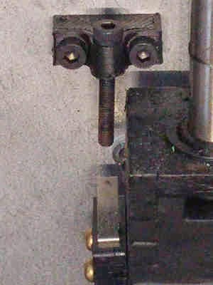
Adjust Z-axis stop or else the printer *will* plow the print head nozzle into the print bed. The E3D v6 hotend in the Lawsy extruder assembly extends about 5mm-8mm further down than the original Solidoodle 2 Pro extruder. I found my original Z-stop bracket and bolt to be just barely long enough to work correctly. If you would make you feel better, then you can use either a longer M3 bolt or an extended Z-stop bracket. After carefully doing this, then redo the Z-axis calibration, leveling the print bed.

Repetier-Host configuration
Dimensions / Printer Shape
Depending on how well or poorly you rewired things, the printer might not be able to print on the same dimensions as before. I had to set an X-Min (X-axis minimum extruder coordinate/position, in millimeters) of 40 in order to avoid catching my extruder wiring on one of the belt bolts. You have also definitely lost some Z-axis capacity/height, so that figure will have to shrink in the Repetier-Host printer settings. I went ahead and dropped mine from 150 to 140 to be safe.
– Printer Settings > Printer Shape

Nozzle Size
The original Solidoodle 2 Pro printers came with a 0.35mm nozzle installed. If you changed your nozzle size then you need to change the Slic3r configuration accordingly.
– Slic3r > Slic3r > Configure > Printer Settings > [new profile] > Extruder 1 > Size > Nozzle diameter > input the exact diameter of your installed nozzle
– Slic3r > Slic3r > Configure > Print Settings > [all profiles] > Advanced > Extrusion width > input 120% of your installed nozzle’s diameter (the plastic expands after it exits the extruder [1])
Temperatures
– Printer Settings > Printer > Default Extruder Temperature > input “230” instead of “200” °C
– Slic3r > Slic3r > Configure > Filament Settings > [all profiles] > Temperature (°C) > Extruder: > First layer and Other layers > input temperatures about 30°C higher than you were using before
- My source material indicated that Custom G-code overrides the Filament settings and thus the temperature(s) need to be modified in the lines starting M104 and M109. However, I had no custom G-code.
– Slic3r > Slic3r > Configure > Printer Settings > [all profiles] > Custom G-code > Start G-code
Calibration
You have substantially messed with your 3d printer. All the things should be calibrated again. 🙁
– If you have banding in your prints, then there is additional calibration you can do to fix that.

References
Sources
Primary
Secondary
- “How to Assemble Acrylic Extruder” on the Solidoodle Wiki, accessed 2015/04/30
- Home / Electrical & Electronics / Wiring Projects / Electrical Tools & Supplies / “8 Ways to Heat Your Heat Shrink Tubing” on DoItYourself.com, accessed 2015/04/30
- “Guide for installing E3D v6 on solidoodle 2 with rev-e board?” by illknowwhenigetthere (
 ), on Reddit (3Dprinting subreddit), 2014/12/06
- “E3D v5 Assembly Manual” by David Lamb and Sanjay Mortimer, on E3D-Online, accessed 2015/04/30
- “E3D Hot End Kit – V6” on Printed Solid, accessed 2015/04/30
- SoliForum – 3D Printing Community → Hacks & Mods → “E3D v6 Solidoodle 2 Bowden” thread by various users, on SoliForum, 2014/09/04
- Customer Service & Technical Support > Software > Drivers/Firmware/Gerbers/STL Files > “Installing Drivers” by Solidoodle Support, on Solidoodle.com, accessed 2015/04/30
- “E3D v6 Information, Installation Guides, and Review” by Mike Kelly (forum profile), on ROBO 3D, 2014/10/23
- “Getting Started with Arduino on Windows” on Arduino.cc, accessed 2015/04/30
Troubleshooting
Services, Tools, and Resources